Quickstart
Power Up
Connect the provided USB-C cable into the Uberlogger and plug the other end into your PC or a USB charger that provides 5V and at least 300 mA. Flip the power switch to on and you should see a green LED light up. Switch the power switch to the on state. The green LED should turn on.
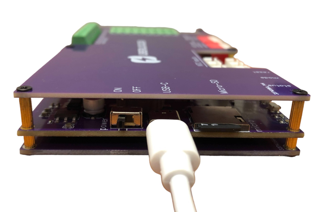
Figure 1: connecting the Uberlogger with the USB connector.
Connect to Wi-Fi & accessing the portal.
From your PC, connect to the Wi-Fi network that reads as
Uberlogger-XXXXXXXX, where XXXXXXXX represents your unique Uberlogger ID.
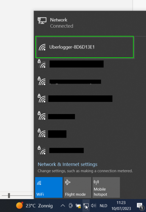
Once connected, open your preferred browser, and navigate to http://192.168.4.1. You should now be viewing the Uberlogger live data page.
Out of the box, the hotspot is open (no Wi-Fi password) and the web
interface requires no login. Both can optionally be secured later
from the Configuration → Network
page. If a login has been configured, the browser will prompt for the
username admin and the password you set.
Starting and stopping logging
Put an SD card formatted as FAT partition into the SD card slot on your Uberlogger.
Currently only SD cards up to 32GB and FAT are supported.
- Start logging Start the logger by either:
By default the Uberlogger is set to "Continuous measurement" mode. With this you can do the following to start the logger.
-
Pressing the "mode" button on the side of the Uberlogger for about 1 second to start logging.
-
Pressing "Start logging" on the top right corner of the user interface:

- Going to the
File browsertab inside the and click on "Start logging":
The green LED on the Uberlogger should blink at an interval of around 1 second to indicate it is logging.

-
Stop Logging: When you are done, you can stop logging by:
-
Pressing the mode button for 1 second
-
Pressing the stop logging button in the top right corner:
-
- Clicking "Stop logging" under the
File browsertab:

Retrieve your data
Your logged data can be retrieved in the following way.
- Ejecting the SD card: before you can eject your SD card, you
need to unmount the SD card by hitting the "eject" button
 at the top
of the page or by pressing "unmount" on the
at the top
of the page or by pressing "unmount" on the Loggingtab. After this you can insert the SD card into a PC and retrieve the data from there.
Do not manually eject the SD-card while the SD-card is mounted and/or while logging. Failing to do so may corrupt your data!
- Using the file browser: you can download the csv from the file
browser which can be found under the
File browsertab. This will always show the last page of the files in the directory.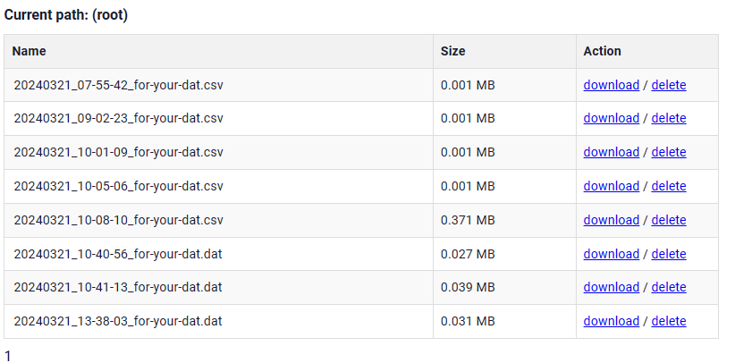
Connecting inputs
Analog inputs
For analog inputs, connect to AINx and its corresponding GND. Each analog input has a ground signal indicated
as GND opposite of the signal as indicated in the figure.
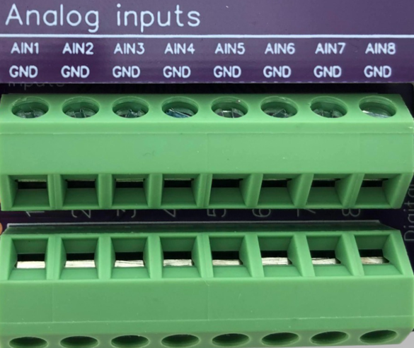
You can connect the analog channel to AINx and its corresponding GND, which is opposite of the positive terminal as indicated above in red. The GND and AINx terminal can handle voltages up to -60V and +60V, respectively. You can insert the wire in the screw terminal by first screwing the terminal open, inserting the wire and then screwing it tight.
NTC inputs
Below are the NTC connector inputs shown. The top ones are NTC1 till NTC4. Bottom row NTC5 till NTC8
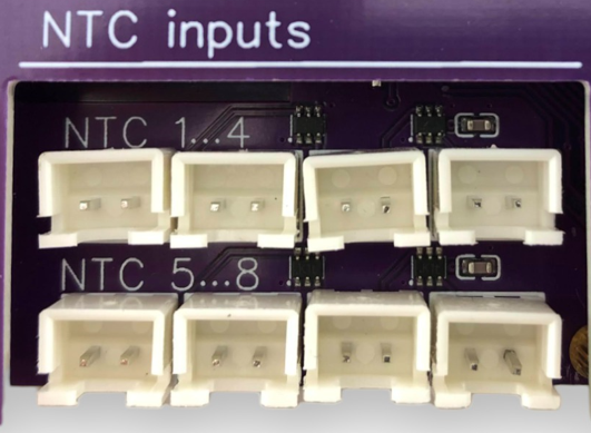
In case you want to use the NTC, you can plug it directly into the socket you want to. The top 4 connectors are connected to channel 1 to 4 and the bottom 4 connectors to channel 5 to 8, respectively.
Digital inputs
Digital inputs have the ground to the left of its digital
channel.
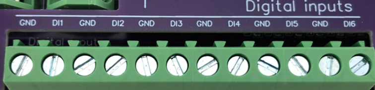
One digital channel terminal pair is shown above, where the GND of DIx is left of the positive terminal. Note that the digital inputs can handle voltages of maximal +/- 60V.